|
|
|
|
|
|
Product Details:
Payment & Shipping Terms:
|
| Material: | Stainless Steel | DN: | 100~400 |
|---|---|---|---|
| PN: | I.0PMa、1.6PMa、ANSI150LB | Temperature Range: | -29℃~100℃、-29℃~30℃ |
| High Light: | hydraulic control valve,water flow control valve |
||
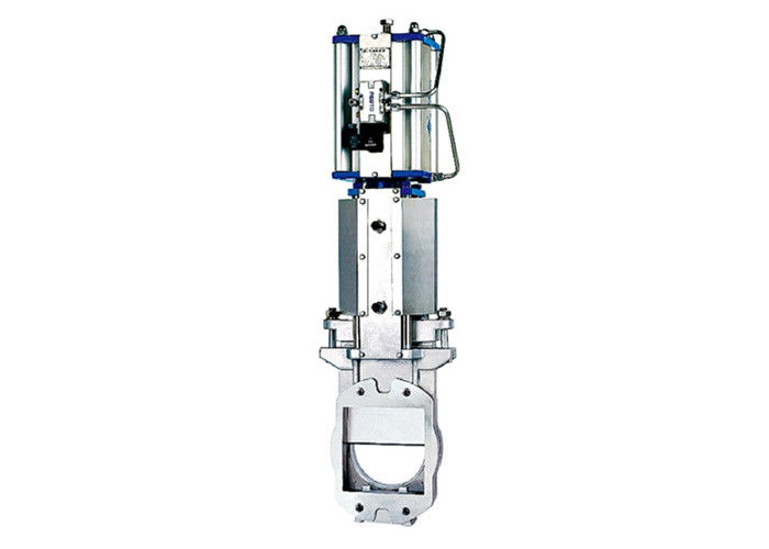
DF series square gate valve
Application
DF series square gate valve is a kind of pneumatic shut-off valve used in the production process of pulping, mud, slag discharge and sewage treatment. It is especially suitable for high concentration slag remover in paper production, heavy material separator, hydraulic pulper and other equipment for slag discharge.
Feature
1. The flow resistance is small, and direct current is formed with the pipe when the gate disc is fully opened.
2. The valve body adopts a two-piece structure with no cavity in the body and is not easy to accumulate.
3. Good sealing, smooth movement, no vibration, and no noise.
4. The sealing seat is designed for the movable structure and has anti-wear and automatic compensation functions, so the service life is long.5. The sealing seat is made of metal seal and EPDM, PTFE soft seal structure, which can be applied to various working conditions.
Technical Parameters
Nominal diameter (DN): 100~400
Nominal pressure (PN): I.0PMa,1.6PMa,ANSI150LB
Temperature range: -29℃~100℃,-29℃~30℃
Air pressure: 0.5~0.7MPa
Connection method: clip type
Main part material
| Valve body | WCB | C F8 | CF8M |
| gate disc | 410+Cr | 304+Cr | 316+Cr |
| Valve seat | 304+Cr/STL | 304+Cr/STL | 316+Cr/STL |
| Cylinder shaft | 45#+Cr | 45#+Cr | 45#+Cr |
| Packing | PTFE/ graphite | ||
| Applicable medium | Sewage, pulp, syrup, slag, etc. | ||
![]()
Pneumatic square gate valve size chart
| DN(mm) | A | L | E | H |
| 100 | 51 | 100 | 220 | 650 |
| 125 | 57 | 125 | 250 | 730 |
| 150 | 57 | 150 | 270 | 820 |
| 200 | 70 | 200 | 350 | 1040 |
| 250 | 70 | 250 | 410 | 1230 |
| 300 | 76 | 300 | 470 | 1390 |
| 350 | 76 | 350 | 550 | 1590 |
| 400 | 89 | 400 | 620 | 1750 |
![]()
Size of square end connection
| DN(mm) | 100 | 150 | 200 | 250 | 300 | 350 | 400 |
| L | 100 | 150 | 200 | 250 | 300 | 350 | 400 |
| M | 180 | 230 | 280 | 340 | 400 | 450 | 500 |
| N | 70 | 95 | 122.5 | 150 | 124 | 137 | 154 |
| Ni | 70 | 95 | 112.5 | 150 | 186 | 205.5 | 231 |
| φH1 | 14 | 14 | 14 | 14 | 14 | 18 | 18 |
| Ant | 8 | 8 | 8 | 8 | 12 | 12 | 12 |
| Lk1 | 90 | 140 | 140 | 150 | 167 | 165 | 155 |
| φ D1 | 100 | 150 | 200 | 250 | 300 | 350 | 400 |
Flange end connection dimensions
| PN10 | |||||||
| DN(mm) | 100 | 150 | 200 | 250 | 300 | 350 | 400 |
| φD | 220 | 285 | 340 | 395 | 445 | 505 | 565 |
| R | 90 | 120 | 147.5 | 175 | 200 | 230 | 257.5 |
| V | 45 | 45 | 45 | 30 | 30 | 22.2 | 22.5 |
| V/2 | 22.5 | 22.5 | 22.5 | 15 | 15 | 11.25 | 11.25 |
| φH2 | 18 | 22 | 22 | 22 | 22 | 22 | 26 |
| Ant | 8 | 8 | 8 | 12 | 12 | 16 | 16 |
| ANSI Class 150 | |||||||
| DN(mm) | 100 | 150 | 200 | 250 | 300 | 350 | 400 |
| φD | 224 | 280 | 340 | 405 | 480 | 530 | 597 |
| R | 95.25 | 120.65 | 149.2 | 180.95 | 215.9 | 238 | 270 |
| V | 45 | 45 | 45 | 30 | 30 | 30 | 22.5 |
| V/2 | 22.5 | 22.5 | 22.5 | 15 | 15 | 15 | 11.25 |
| φH2 | 18 | 22 | 22 | 26 | 26 | 30 | 30 |
| Ant | 8 | 8 | 8 | 12 | 12 | 12 | 16 |
| JIS B2238 | |||||||
| DN(mm) | 100 | 150 | 200 | 250 | 300 | 350 | 400 |
| φD | 224 | 280 | 340 | 405 | 480 | 530 | 550 |
| R | 87.5 | 120 | 145 | 177.5 | 200 | 222.5 | 255 |
| V | 45 | 45 | 30 | 30 | 22.5 | 22.5 | 22.5 |
| V/2 | 22.5 | 22.5 | 15 | 15 | 11.25 | 11.25 | 11.25 |
| φH2 | 19 | 23 | 23 | 25 | 25 | 22 | 27 |
| Ant | 8 | 8 | 12 | 12 | 16 | 16 | 16 |
![]()
A special flange converter is required to install the square knife gate valve. One end is a square port connected to the square port of the square knife gate valve, and the other end is a standard flange connection port connected to the pipe flange.